Foundation Licence Manual for Radio Amateurs
by Alan Betts, G0HIQ
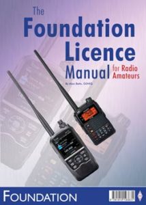
The Foundation Licence Manual for Radio Amateurs is the RSGB course-book for those who wish to become radio amateurs in the UK. In line with the progressive three-tier UK licence structure, the Foundation Licence Manual is the first step in the natural progression to the Intermediate and Full licence.
This book sets out to provide the very latest information required to obtain a UK Foundation licence. Broken down into 15 easy to digest sections Foundation Licence Manual for Radio Amateurs covers all you will need to know to be successful in the examination. This book provides insight into technical basics, receivers, transmitters, antennas, feeders and propagation. There are details of the operating practices & procedures you will need to know alongside safety considerations, electromagnetic compatibility and licence information. The practical assessments are explained and there is a helpful guide to how to best approach the Foundation examination itself.
Written in an easy to understand style by acknowledged exams expert Alan Betts, G0HIQ the Foundation Licence Manual for Radio Amateurs is the ideal book for those coming to amateur radio for the first time.
This book is obsolete as of the 31st August 2024
and has been replaced by a 3rd Edition
no further updates will now be posted
Corrections and updates
We are currently shipping a 2nd edition of this book marked ‘Printed 2022’ and currently this has no reported corrections or updates.
As of the 1 September 2022 the Exam syllabus used by the examinations will be version 1.5. The changes made to the syllabus primarily concern the introduction of the requirement for all amateurs to check compliance with EMF (Electromagnetic Field) exposure limits. The current edition of the Foundation Licence Manual is compliant with syllabus 1.5. For those using previous editions of the book we have provided a supporting leaflet that details these important changes, this can be obtained as a free of charge download from here.
Practical Assessments
For all previous printings of this book any reference to Practical Assessments can be ignored as these have now been removed from the syllabus.
Errata to the previous 2019 printings.
Some of these changes below were made to the various reprints of this book in 2019. As there are various 2019 printings in circulation, it is worth checking your copy against the updates below.
Page 4, Electrical Circuits
Please replace Fig: 3.1 with the one below

New Caption: Fig 3.1: The circuit symbols for a cell and a battery of cells. The longer side is the positive connection.
Page 5, Uses for resistors
Please replace Fig: 3.6 with the one below
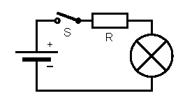
New Caption: Fig 3.6: An electric circuit with some added resistance R and a switch S.
Page 6, A light emitting diode circuit
Please delete the final paragraph in this section (column 3, paragraph 2).
Page 10, Sidebands
Second last paragraph should be amended to start with ‘Inspection of Figs 4.5 and 4.6….’ (column 2, paragraph 3).
Page 13, The Yagi
Please amend the last sentence of the final paragraph in this section (column 3, paragraph 6) to read ‘This can be converted to the actual gain by using Table 6.1’ and insert the table below.
|
Gain in dB |
Gain – times |
|
3 |
2× |
|
6 |
4× |
|
9 |
8× |
|
10 |
10× |
|
12 |
16× |
Caption: Table 6.1: Gain in dB and antenna gain for erp calculations.
Page 19, Intermediate
The two example callsigns are incorrect, please replace with 2E0XYZ and 2M0ABC (column 3, paragraph 1).
Page 20, 1A5 Recall the requirements for station identification
The example callsign in the explanation is incorrect, please replace with MW7XYZ/M (column 3, paragraph 3).
Page 27, Signal reports
Please amend the last sentence of the first paragraph in this section (column 2, paragraph ) to read ‘A handy RST chart is shown in Table 9.2’ and insert the table below.
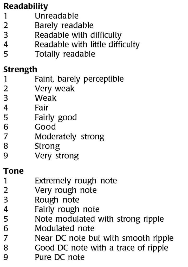
Caption: Table 9.2: The RST code for reporting signal reception.
Page 28, Repeaters
Please amend the first sentence of the third paragraph in this section (column 1, paragraph 5) to read ‘Take a look at the 144MHz band plan shown in Fig 9.1’.
Page 30, How is interference caused?
Please amend the caption on Fig 36 to read Fig 10.1
Page 31, Earthing
Please insert the figure shown below

Caption: Fig 10.2: The Earth symbol
(re-number subsequent figures accordingly and amend the figure references in the text)
Page 33, Mains plugs, earths & fuses
Please insert the figure shown below
![]()
Caption: Fig 11.2: The Fuse symbol
(re-number subsequent figures accordingly and amend the figure references in the text)
No other corrections have been reported at this time
Category: Books Extra

