
Backyard Antennas

Antenna guru Peter Dodd explains how, by using a variety of simple techniques, it is possible to achieve very high performance from a compact antenna.
Click cover picture to buy this online.
Corrections, updates and additional information
Backyard Antennas. Addendum and Errata to the Second Reprint (8 November 2004).
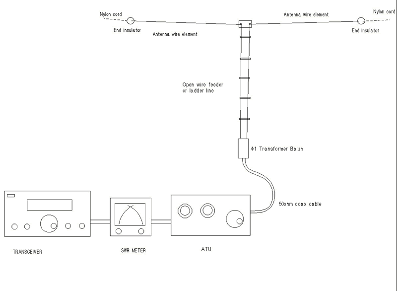
THE COMUDIPOLE (coaxial cable fed multi-band dipole)
This antenna arrangement shown in on pages 26 and 27 has proved to be a very useful solution for many restricted sites. However, the diagram implies that the balun unit must be placed close to the antenna.
In fact the balun can be placed anywhere along the transmission line section from the antenna to the ATU as shown in Fig 3.
In practice the feeder system should consist mainly of twin wire feeder or ladder line because the losses on such line with a high SWR are much lower, see diagram (Fig 9.7) on page 151.
Note that twin wire feeder performance can be affected by the close proximity of metal objects such as metal windows or guttering.
The antenna is then not that much different from the tuned open wire dipole arrangement shown on page 24 (Fig 2.11) but the commudipole overcomes the problem of running twin line feeder into the shack because the balun can be located outside the shack.
A suitable balun is described on page 45/46 (Fig 4.4). If you are restricted to a short dipole antenna, say less than 15m (45ft), then a 1:1 balun might be more appropriate.
The arrangement shown in (Fig 4.4) can be set up for ratios of 4:1 or 1:1.
REFERENCES
(nothing further added)
GENERAL ERRATA
Fig 7.22, page 120. This drawing implies that Yagis 2 and 4 are fed 180 degrees out of phase with Yagis 1 and 3. The driven elements of all Yagis must be fed in phase.
Fig 9.7, page 151. The first value of transmission loss on the vertical scale should be 0.5db rather than .05 as shown. Fig 9.7 caption, second line. 10m should read 30m. The (100ft) is correct.
Fig 3. The Comudipole feed arrangement for a multiband doublet antenna
First Print:
Page 63, Heading to Table 4, G3OLB should be G0LMJ
References, Page 67, G0OUJ should be G0LMJ
The Moxon Rectangle antenna, described on Page 99, came from W4RNL’s website. This antenna works well as a single band antenna but tests done subsequent to publication indicate that the antenna does not appear to function in a multiband configuration, as shown in Fig 6.18. This is probably due to the coupling between parasitic and driven elements being more critical than in the VK2ABQ, or the Double-D antenna shown in Fig 6.21, where a multiband configuration appears to work when tuned for optimum performance.
The Moxon Rectangle can be converted to a VK2ABQ by arranging the element supports, shown in Fig 6.18, so that they are at 90 degrees to each other (the antenna elements are in a square configuration). Use the element dimensions shown in Table 6.4.
A full discussion of the Moxon Rectangle and multibanding can be found at www.cebik.com/moxpage.html. Note that this site replaces that shown in reference [6] on page 107.
Page 115. The dimensions for Table 7.1 are for one side of the quad rather than the whole element length as shown in the UHF “circular” quad in Fig 7.16 on the same page.
Fig 7.22, page 120. This drawing implies that Yagis 2 and 4 are fed 180 degrees out of phase with Yagis 1 and 3. The driven elements of all Yagis must be fed in phase.
Fig 9.7, page 151. The first value of transmission loss should be 0.5db rather than .05 as shown. 10m, in Fig 9.7 title should be 30m.
Category: Books Extra